Electrical and Hybrid Powertrains Demand Galvanic Isolation
The chassis is a common ground potential for all 48-volt ECUs in the car. As the chassis has a non-zero impedance, a significant return current will be conducted through it, and a portion of this return current will find its way through a parallel path: the copper cables‘ shielding. An OEM has stated that the shield of Shielded Twisted Pair (STP) cables can conduct more than 8A of return current due to the 48-volt jump start effect.
In addition, the need for a ubiquitous communications network within the vehicle, and particularly between ECUs belonging to different voltage domains, represents a source of potential hazards. Thus, it imposes the additional requirement of galvanic isolation between the communicating nodes. Any event that could cause the 48-volt to cross into the 12-volt might destroy the ECUs in the 12-volt domain, provided the line transceivers do not provide sufficient galvanic isolation.
With regulations driving car companies to reduce Greenhouse Gas (GHG) emissions further by 2021, a new hybrid architecture concept based on a two-voltage power line (12-/48-volt) is already in the advanced marketing announcements of OEMs and Tier-1. As a further example of this new industry-wide technological trend towards 48V power supply and the handling of it, the German VDA published recommendation 320, which covers electric and electronic components in vehicles for the development of a 48-volt power supply. It defines requirements, test conditions and tests performed on electric, electronic and mechatronic components and systems for use in motor vehicles with a 48-volt on-board power supply.
48 Volt Jump-start Parasitic High Energy Pulse
48-volt-based energy networks or mixed 12/48 volt topologies are and will keep being the mainstream of HEV and Plug-in Hybrid Electrical Vehicle (PHEV) powertrains. The electrical ground, which is connected to the vehicle chassis and is common to high and low voltage ECUs, creates problems on start-up events that are continuously taking place in such powertrains. For example, the infotainment system shares the electrical ground with the energy generation and control systems. The high return currents flowing through the chassis on start-up couple into the infotainment low-voltage system through the cable shielding, which is connected to the same electrical ground of the vehicle. Copper-cable shielding provides a parallel return path (alternative to the chassis) for the currents of the diverse ECUs. Due to this, currents higher than 8 ampere can be measured in the cable shielding during a typical jump start. If the communications link between the ECUs in the low-voltage systems like infotainment or ADAS is optical, then the native galvanic isolation will isolate them from the high voltage/high energy systems and their associated events, thus preserving their reliability.
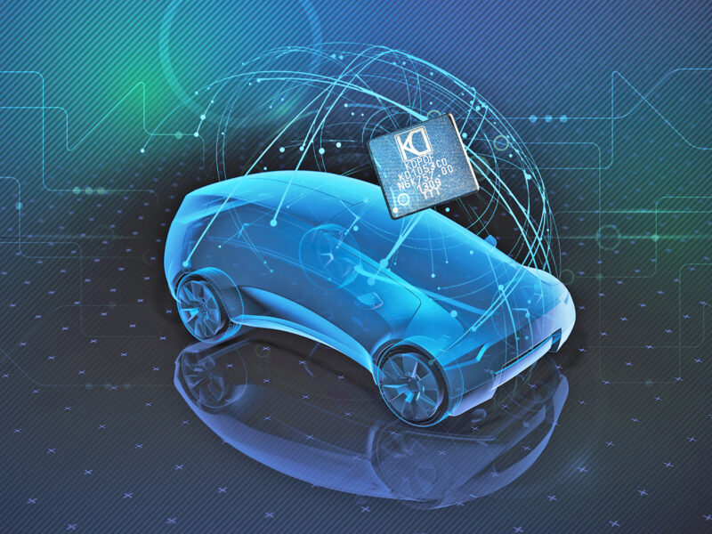
The graphics show the chassis of a car that uses 48 volt as the voltage level to power the different electronic units which are included in different areas. In this case, two electronic units (ISG/BMS and FRAD) are shown in two different places of the car; however, they are electrically connected through the chassis, which has certain parasitic resistance (0.5 milliohm). The graphics also show two head units that correspond to the infotainment system in the car. They are also connected to the chassis through different ground trees, and between them by a shielded twisted pair (copper).


which couples into STP data link.


EMC Compliance
EMC qualification is one of the critical steps of a platform validation by TIER-1 and OEMs. Copper links for communication rates above 100 Mbps need sophisticated and expensive solutions to comply with the stringent carmaker’s EMC specs: high-quality shielding, controlled pair twisting, complex in-line connectors, etc. Optical ports can pass both EMI and EMS much more easily. This directly impacts the cost of the harness and the connectors, not to mention the engineering resources assigned to the development and debugging stages.

Gigabit Ethernet POF (GEPOF), provide the optimal means to achieve
galvanic isolation.
Automotive Gigabit Ethernet Transceiver
POF has been present in vehicles for more than 10 years and is installed in millions of cars. POF cables are extreme reliable: they can tolerate harsh environments, vibrations, misalignments, dirtiness, humidity, wide temperature range, etc. Furthermore, they allow fast dynamic bending, tight static bending radiuses, and immersion in liquid.

and thus fully meets the requirements of carmakers.
Spanish Startup KDPOF provides a fully integrated automotive transceiver that implements the physical layer of Gigabit Ethernet over POF (GEPOF). Data transmission of the KD1053 device is at 1000/100 Mbps on standard SI-POF, MC-POF, or PCS, according to 1000BASE-RH (IEEE Std 802.3bvTM-2017). Its flexible connectivity supports multiple digital host interfaces (MII, RMII, RGMII, SGMII, 100/1000BASE-X), SMI (MDC/MDIO) interface for configuration and monitoring supporting Clauses 22 and 45, which can also be configured as an I2C bus and SPI/I2C master interface for reading external boot and configuration EEPROM memory. The transceiver also supports OAM, Wake-up & Sleep, interruption generation, as well as jumbo packets up to 10 KB, PTP, and SyncE clock generation.
It offers different loopback modes, PMD test modes for diagnostics, link/activity monitoring, and speed LED outputs. Digital adaptive non-linear equalizers are fully integrated. Bit Error Rate (BER) is < 10-12 for 1 Gbps and 100 Mbps operation modes. Latency is 6.2 ms for 1 Gbps operation and 1.4 ms for 100 Mbps (local RGMII to remote RGMII); and 5 ns RMS jitter for 1 Gbps operation and 9 ns for 100 Mbps. Link time for 1 Gbps operation totals 55 ms. Internal dependability functions include power supply voltages, temperature sensors, local and remote link margin, and FOT input power monitoring. Of further benefit is the advanced power management with integrated linear voltage regulators. Also, the KD1053 consumes low power of 460 mW at 1 Gbps with serial interface. It has a low-cost bill of materials (BOM). KDPOF has designed the IC to be compliant with the most stringent EMC specs of the OEM, providing Automotive AEC-Q100 grade 2, -40 to +105°C ambient temperature range, and 56-pin QFN (7 x 7 mm) ROHS package. Consequently, it fully meets the demands of carmakers.
About the author: Óscar Ciordia is Marketing Director with KDPOF
 If you enjoyed this article, you will like the following ones: don't miss them by subscribing to :