Designing mmWave radar systems for next-gen smart vehicles
However, higher frequency propagation comes with greater path loss, as isotropic free-space attenuation is inversely proportional to wavelength. In addition, along with this additional path loss, as wavelengths get smaller, physical processes such as diffraction, scattering, and material penetration loss make the channel properties of mmWave bands significantly more challenging.
Phased-array beamforming produces a directive beam that can be repositioned (scanned) electronically in order to overcome these greater channel losses. Beam-steering techniques such as minimum variance distortion-less response (MVDR) also improve target (road obstacle) identification.
Radar designers view the array antenna as a component with measurable input and output, and a set of specifications. Array designers see the details of the array and the physical and electrical limitations imposed by the radar system. Both must work together to achieve the goals of these very complex systems.
In addition, like their aerospace and defense-related counterparts, ADAS must perform over a range of operating conditions and object detection challenges in order to provide reliable coverage over the range (distance) and field of view (angle) as dictated by the particular driver assist function. Unlike the antenna systems developed for aerospace and defense applications, they must be designed for cost-effective, high-volume deployment.
This white paper examines several challenges behind developing mmWave radar systems for the next generation of smart cars and trucks and looks at new capabilities recently added to electronic design automation (EDA) software that supports a design flow for developing high-performance arrays that are also cost and space conscious. The radio-frequency (RF) front-end hardware supporting these new antenna systems must be optimized for performance, reliability, compactness, and cost.
The individual components must be specified and developed through a design flow that manages and combines this performance data in order to achieve accurate simulation of the overall array and feed structure across scan region, frequency range, and other operational requirements. This flow should also provide a pathway to physical realization of the individual components, including the antenna array itself.
An enhanced phased-array generator wizard within the NI AWR Design Environment platform enables users to interactively develop phased-array antenna systems and generate array and feed network schematics or system diagrams suitable for further circuit/system/EM analysis. Users can easily define the array geometry (configuration), feed structures, gain tapers, and characteristics of individual elements and their respective RF links.
This wizard works interactively with NI AWR software tools, inclusive of Microwave Office, Analog Office, Visual System Simulator™ (VSS), AXIEM, Analyst™, and AntSyn™ software, to guide phased-array/feed network component/system development from concept to product.
Overview of ADAS
Automobile manufacturers are equipping new models with ADAS based on vision sensor technology and radar systems operating at 24 and/or 77 GHz. Long-range radar (LRR) supports multiple functions, comfortably handling distances between 30 and 200 meters, while short-range radar (SRR) can detect objects below 30-meter distances. The 77-GHz band (from 76 to 81 GHz), currently supporting LRR is expected to provide both short- and long-range detection for all future automotive radars. Figure 1 shows the different ADAS functions and ranges.
Advances in radar modulation techniques, antenna beam-steering, system architecture, and semiconductor technology are driving the rapid adoption of mmWave radar in future ADAS-enabled cars and trucks. Meanwhile, the technical advantages of the 77-GHz band include smaller antennas (a third of the size of the current 24-GHz ones), higher permitted transmit power, and, most importantly, wider available bandwidth to enable higher object resolution.

Designing components to operate at higher frequencies, however, is inherently more difficult. To drive the adoption of these technologies, radar developers require RF-aware system design software that supports radar simulations with detailed analysis of RF front-end components, including nonlinear RF chains, advanced antenna design, and channel modeling.
Co-simulation between circuit and EM analysis provides an accurate representation of true system performance prior to building and testing costly radar prototypes. NI AWR software provides these capabilities, all within a platform that manages automotive radar product development—from initial architecture and modulation studies through the physical design of the antenna array and front-end electronics based on either III-V or silicon integrated circuit (IC) technologies.
The NI AWR Design Environment platform integrates these critical radar simulation technologies while providing the necessary automation to assist the engineering team with the very complex task of managing the physical and electrical design data associated with ADAS electronics. Figure 2 shows the various NI AWR software tools that support ADAS development.

NI AWR software tools and functionality that support phased-array design include:
System Simulation – The design of waveforms, baseband signal processing, and parameter estimation for radar systems with specific analyses for radar measurements, along with comprehensive behavioral models for RF components and signal processing. The component and array/antenna requirements are determined using system-level link analysis.
Circuit Simulation – The design of transceiver RF/microwave front-ends with circuit-level analyses and modeling (distributed transmission lines and active and passive devices) to address printed circuit board (PCB) and monolithic microwave integrated circuit (MMIC)/RFIC design.
EM/Antenna Simulation – Planar/3D electromagnetic (EM) analysis for characterizing the electrical behavior of passive structures, complex interconnects, and housings, as well as antennas and antenna arrays. Antenna synthesis generates a physical antenna design based on performance specifications.
Phased-Array Generator Wizard – Supports array configuration, early analysis of array using radiation pattern for individual array elements, and feed network based on user input, generating circuit/system schematics and test benches for further analysis.
Radar architectures and modulation
For adaptive cruise control (ACC), simultaneous target range and velocity measurements require both high resolution and accuracy to manage multi-target scenarios such as highway traffic. Future developments targeting safety applications like collision avoidance (CA) or autonomous driving (AD) call for even greater reliability (extreme low false alarm rate) and significantly faster reaction times compared to current ACC systems, which utilize relatively well-known waveforms with long measurement times (50 – 100 ms).
Important requirements for automotive radar systems include a maximum range of approximately 200 m for ACC, a range resolution of about 1 m and a velocity resolution of 2.5 km/h. To meet all these system requirements, various waveform modulation techniques and architectures have been implemented, including a continuous wave (CW) transmit signal or a classical pulsed waveform with ultra-short pulse length.
There are many tradeoffs to be considered when deciding which architecture and waveform modulation technology delivers the necessary performance while maintaining development and production cost goals. These requirements can be investigated most efficiently with commercially-available software dedicated to RF system design and implementation, offering the necessary simulation technologies and radio block/signal processing models, along with design automation, to manage complex product development.
VSS system design software provides the simulation and detailed modeling of RF and digital signal processing (DSP) components necessary to accurately represent the signal generation, transmission, antenna, T/R switching, clutter, noise, jamming, receiving, signal processing, and channel model design challenges and analysis requirements for today’s advanced radar systems. VSS software provides the critical system-level link analysis needed to determine the individual component performance requirements, including the array/antenna.
In addition, the optional VSS phased-array generator wizard enables designers to specify key electrical/physical attributes of the array, including number of elements, distance between elements, coupling between elements (along with edge and corner behavior), frequency, geometry of the array, and radiation pattern for each element or groups of elements
Users can organize radiating elements into groups and assign different antenna radiation details and RF link properties to individual elements or multiple elements at a time, usually based on location within the array, such as an edge or corner. This capability helps simplify and expedite the process of setting up arrays with many elements by scaling element/feed details to the entire array using a smaller, more manageable number of element groups. Elements within the same group may then be assigned an antenna and/or RF link configuration from among multiple user-defined configurations.
Generating designs from the wizard
One goal of the phased-array generator wizard is to provide designers with a powerful yet intuitive interface to define a physical-array configuration, assign antenna and RF link characteristics to individual and/or groups of elements, define feed networks and gain taper properties, and simulate the response, inclusive of potential element failure (Figure 3). This enables users to produce a far-field plot that can be swept for frequency, input power, and phi and theta angles using slide tuners to control these parameter values. The resulting antenna pattern view provides designers with a real-time visual aid depicting the impact of design decisions on far-field performance.

Developing actual phased-array hardware requires the design and simulation focus to shift toward circuit-level analysis and physically-realizable components. The entire available design flow, from antenna synthesis, generation of antenna radiation patterns through EM analysis, configuration of the array and feed network, and generation of circuit or system-based schematic design is shown in Figure 4.

Antenna design
A multi-modal radar for an ACC system [1] based on a frequency-modulated CW (FMCW) radar driving multiple antenna arrays is shown in Figure 5. This multi-beam, multi-range radar with digital-beam forming operates at both 24 and 77 GHz, utilizing two switching array antennas to cover long range and narrow angle coverage (150 m, ±10∞) and short-range and wide-angle coverage (60 m, ±30∞).
This example illustrates the use of multiple antenna-array systems that were required for this type of system, including multiple (5 x 12 elements) series fed patch antennas (SFPAs) for the long range, narrow angle detection (77 GHz), a single SFPA (1 x 12 elements designed for 24 GHz) for short, wide angle detection, and four (1 x 12) SFPAs for the receiver.
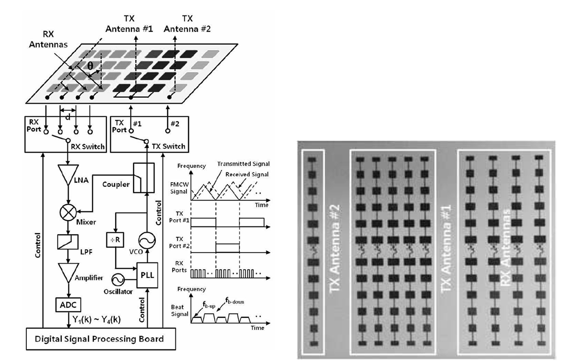
Radar performance is greatly influenced by the antenna technology, which must consider electrical performance such as gain, beam width, range, and physical size for the particular application. The multiple, fixed TR/RX antenna arrays in this radar were optimized for range, angle, and side-lobe suppression. A patch antenna is relatively easy to design and manufacture and will perform quite well when configured into an array, which results in an increase of overall gain and directivity.
More complex geometries may be developed to improve performance or address aggressive size constraints. For these instances, the AntSyn antenna synthesis tool can be applied to help the designer more fully explore design possibilities and develop improved performance based on novel geometries. AntSyn software generates physical designs from a set of antenna requirements specified by the designer using a proprietary genetic-algorithm based optimizer and fast EM solver to realize actual physical computer designs ready for further EM analysis and development.
The performance of a simple rectangular patch antenna design is controlled by the length, width, dielectric height, and permittivity of the antenna. The length of the single patch controls the resonant frequency, whereas the width W controls the input impedance and the radiation pattern.
By increasing the width, the impedance can be reduced. However, to decrease the input impedance to 50 ohms often requires a very wide patch antenna, which takes up a great deal of valuable space. Larger widths also can increase the bandwidth, as does the height of the substrate h. The permittivity of the substrate controls the fringing fields with lower values, resulting in wider fringes and, therefore, better radiation.
Decreasing the permittivity also increases the antenna’s bandwidth. The efficiency is also increased with a lower value for the permittivity. A faster and more efficient means to investigate these tradeoffs is to utilize the powerful EM-based optimization in AntSyn software to determine candidate antenna designs based on electrical performance and size requirements as specified by the designer (Figure 6).

A more rigorous analysis of a single patch antenna or array is made possible through the use of electromagnetic analysis using the AXIEM 3D planar or Analyst 3D finite element method (FEM) simulators. Operating within the NI AWR Design Environment platform, these tools not only simulate antenna performance such as near- and far-field radiation patterns, input impedance, and surface currents, they also co-simulate directly with VSS software, automatically incorporating the antenna simulation results into the overall radar system analysis without the need to manually export/import data between EM simulator and system design tools (Figure 7).

Both AXIEM and Analyst simulators can import the physical geometries generated by AntSyn software or take the user-defined physical attributes of the antenna, such as patch width and length, and dielectric properties such as material and substrate height, to produce the electrical response. AXIEM software is ideal for patch antenna analysis, whereas Analyst software is best suited for 3D structures such as modeling of a coaxial feed structure or finite dielectric (when proximity to the edge of a PCB would impact antenna performance). This is shown in Figure 8.

EM analysis provides the radiation pattern that is used by the phased-array generator wizard to analyze the array performance. EM analysis is also used to verify the performance of the entire array using physical information about the array configuration specified in the phased-array generator wizard and the antenna’s physical information that was generated by AntSyn software.
AXIEM and Analyst simulators also support automatic generation of the radiation pattern data file in the format used by the phased-array generator wizard, providing self-contained projects that are inclusive of the individual antenna element, as well as the entire array/feed network configuration.
Array configuration and feed network definition
With individual elements designed and characterized through EM analysis, users can specify array parameters (size, number of elements, element spacing, shape, and more), organize radiating elements into groups and assign different antenna radiation details and RF link properties to individual or multiple elements at a time, usually based on location within the array, such as an edge or corner.
This capability helps simplify and expedite the process of setting up arrays with many elements by scaling element/feed details to the entire array using a smaller, more manageable number of element groups. Elements within the same group may then be assigned an antenna and/or RF link configuration from among multiple user-defined configurations.
In the phased-array generator wizard, the feed network definition enables the designer to specify the loss between the common port and the antenna element ports, as well as the characteristic impedance, S-parameters, voltage standing-wave ratio (VSWR), or return loss on the common and element ports. In the phased-array configuration, the settings determine the characteristics of the feed network splitter/combiner.
When generating system diagrams, users have the option of specifying either a single splitter block for the entire feed network or a cascade of individual splitters. The loss between common and element ports determines the overall loss between the common port of the feed network and the port of an individual element.
The NI AWR Design Environment platform also provides capabilities for additional design detail and in-depth analysis for further hardware development, including full EM simulation of the entire array, along with co-simulation of the feed structure represented by circuit- and system-level behavioral blocks constructed from information defined by the user in the phased-array generator wizard. The wizard supports the generation of simulation-ready circuit, system, and data file-based designs configured into hierarchical schematics for analysis by Microwave Office or VSS software and the assigned EM simulator.
With the wizard generated array geometry, AXIEM and Analyst simulators or supported third-party EM tools such as HFSS can be used to analyze the entire detailed physical array, with the individual port feeds pre-defined. This enables the design team to investigate the interaction between the beam angle and the input impedance of each individual element, as well as to account for impedance loading effects on transceiver performance (Figure 9). This capability highlights the importance of co-simulation between RF circuit, system, and EM to accurately investigate circuit/antenna behavior before fabricating these complex systems.

MIMO and Beam-Steering antenna technologies
For road vehicles, a radar will receive unwanted backscatter off the ground and any large stationary objects in the environment, such as the sides of buildings and guardrails. In addition to direct-path reflections, there are also multipath reflections between scatterers, which can be used to mitigate the impact of clutter through the use of multiple-in-multiple out (MIMO) antennas.
A MIMO radar system uses a system of multiple antennas with each transmit antenna radiating an arbitrary waveform independently of the other transmitting antennas. Each receiving antenna can receive these signals, however, due to the different waveforms, the echo signals can be re-assigned to the single transmitter.
An antenna field of N transmitters and a field of K receivers mathematically results in a virtual field of K·N elements, resulting in an enlarged virtual aperture that enables designers to reduce the number of necessary array elements. MIMO radar systems thereby improve spatial resolution and provide a substantially improved immunity to interference. By improving the signal-to-noise ratio (SNR), the probability of detection of the targets is also increased.
VSS software is able to implement user-specified MIMO algorithms and evaluate the overall performance as it relates to the channel model, which simulates a highly-customizable multipath fading channel that includes channel-path loss, the relative velocity between the transmitter and receiver, and the maximum Doppler spread.
Supporting independent or continuous block-to-block operation, the channel can contain multiple paths such as line of site (LOS), Rayleigh, Ricean, or frequency shift, that can be individually configured in terms of their fading types, delays, relative gains, and other applicable features. This module can also simulate a receiver antenna array with user-defined geometry, allowing simulation of single-input-multiple-output systems.
The feed network in the phased-array generator can be configured for combined or separate MIMO operations. In the MIMO modes, the elements are treated as standalone elements and are not modeled with any RF circuit connection. For the MIMO combined operation mode, the radiated signal represents the signal received at a point in space from all the elements.
This is essentially the sum of the signal from each of the individual elements at a specified angle of incidence to the origin of the array. For the MIMO separate operation mode, the radiated signal represents the multiplexed separate signal from each individual element. The feed network definition is not utilized for either MIMO configuration.
Conclusion
Advanced driver assistance systems will not only become more sophisticated and reliable as technology develops, they will become more prevalent on most if not all vehicles in the not-too-distant future. Thanks to similar advances in antenna array and mmWave technology that are occurring in 5G communications, most cars and trucks will be considerably safer than today.
Innovations in simulation technology and a new design flow in NI AWR software support RF-aware circuit design, array configuration, modeling/optimization, and system-level co-simulation, enabling antenna designers and system integrators to optimize these systems for challenging size, cost, and reliability targets.
Reference
[1] S.-H. Jeong, H.-Y. Yu, J.-E. Lee, et. al., “A Multi-beam and Multi-range Radar with FMCW and Digital Beam-forming for Automotive Applications,” Progress in Electromagnetics Research, Vol. 124, 285-299, 2012.
 If you enjoyed this article, you will like the following ones: don't miss them by subscribing to :